Dimensions de la typologie
De Opera Wiki.
(→Quote tipologia) |
|||
| Ligne 1 : | Ligne 1 : | ||
__TOC__ | __TOC__ | ||
| - | {{NB| | + | {{NB|To access this panel in Opera Job Management: from the ''Typology General Data'' or ''Design Sheet'' panel, press the [[File:tastoquota.png]] button.}} |
[[File:foglioprogettazionefuorisquadra.png|600 px|thumb]] | [[File:foglioprogettazionefuorisquadra.png|600 px|thumb]] | ||
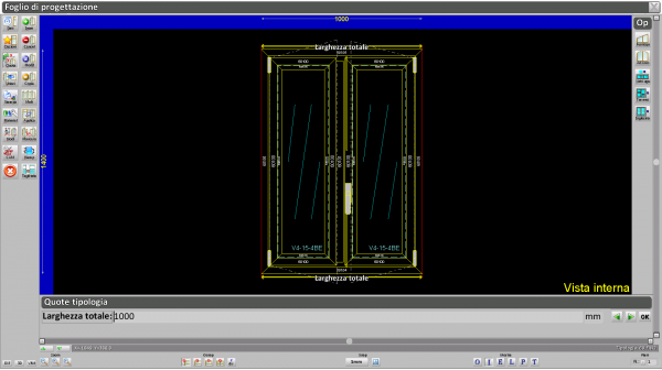
| - | In | + | In this mode, it is possible to specify the dimensions of the typology. You can interact in two areas: Typology dimensions (bottom) and Options (right). |
| - | ''' | + | '''Pressing the button between the arrows toggles the display of the nodes.''' |
[[File:QuoteNodiTasto.png|500px]] | [[File:QuoteNodiTasto.png|500px]] | ||
| - | {{NB| | + | {{NB|To see dimensioning with nodes, you must first [[Visualizzazione Nodi|create the nodes]] in the archive.}} |
{{BR}} | {{BR}} | ||
| - | == | + | |
| + | == Typology Dimensions == | ||
[[File:QuoteNodiLarghezza.png|500 px|thumb]] | [[File:QuoteNodiLarghezza.png|500 px|thumb]] | ||
| - | *''' | + | *'''Total Width and Total Height''': These are the perimeter dimensions of the typology, excluding any overlap flanges (or trims). |
| + | When entering dimensions, you should measure the opening where the typology will be installed, excluding the small clearance between the wall and the frame. However, this clearance can also be defined in the typology as a frame-to-wall gap value, and it will be automatically subtracted. | ||
{{BR}} | {{BR}} | ||
| - | |||
| - | |||
| - | |||
| - | |||
| - | |||
| - | |||
| - | + | *'''Lock height''': This is the height of the lock or handle. The reference point depends on the following button settings:<br> | |
| + | :[[File:altezzaserratura.png]] The height is measured from the '''fixed frame''', '''excluding''' the overlap flange.<br> | ||
| + | :[[File:altezzaserratura2.png]] The height is measured from the '''moving frame''', '''including''' the overlap flange.<br> | ||
| + | :[[File:altezzaserratura3.png]] The height is measured from the '''moving frame''', '''excluding''' the overlap flange. To enable this, the tubular difference must be defined in the profile archive.<br> | ||
| + | :[[File:altezzaserratura4.png]] The height is measured from the '''moving frame''' to the '''chamber'''.<br> | ||
| + | :[[File:altezzaserraturadaterra.png]] Same as the first option, but for composite structures, the reference can be taken from the '''floor'''.<br> | ||
| - | :[[File:tastoaltezzacentr.png]] | + | These buttons should be selected '''before''' entering the lock height value. |
| + | |||
| + | :[[File:tastoaltezzacentr.png]] This button centers the lock based on the selected height reference. | ||
{{BR}} | {{BR}} | ||
| - | [[File:spostamentoanta.png|400 px|thumb| | + | [[File:spostamentoanta.png|400 px|thumb|Reference points for sash width.]] |
| - | *''' | + | *'''Sash displacement''': Refers to the width of each sash in an openable structure. This is only required for structures with more than one sash.<br> |
| - | + | Measurement reference starts from the chamber of the fixed frame on the left (internal view; right if viewed externally) up to the midpoint of the central node gap, as shown in the image. | |
| - | + | ||
| + | Supported by the following buttons: | ||
| + | |||
| + | :[[File:tastoante.png]] Automatically equalizes sash widths, maintaining equal distances between gaps.<br> | ||
| + | :[[File:tastospec.png]] Automatically creates equal light divisions.<br> | ||
| + | :[[File:tastolungh.png]] Enables manual width setting for each individual sash in multi-sash structures. | ||
| + | |||
| + | *'''Sash width''': Forces the width of each sash in an openable structure.<br> | ||
| + | *'''Sash height''': Forces the height of each sash in an openable structure.<br> | ||
| - | |||
| - | |||
| - | |||
| - | |||
| - | |||
{{BR}} | {{BR}} | ||
| - | *''' | + | *'''Box height''': This is the total height of the box (e.g. for roller shutter boxes). |
| + | If it’s a preassembled box, the height is automatically taken from the "Box cap" accessory assigned to the structure. Manual input will not be required. | ||
| - | *''' | + | *'''Horizontal and Vertical dimensions''': These refer to the width and height of a structure that is part of a composite typology. |
| - | {| | + | {| |
|- | |- | ||
| - | |[[File:quotaorizzontale.png|thumb|200px| | + | |[[File:quotaorizzontale.png|thumb|200px|Example of setting a '''horizontal dimension''' (width) for one part of a two-structure typology.]] |
| - | |[[File:QuoteNodiLargCentroTraverso.PNG|thumb|500px| | + | |[[File:QuoteNodiLargCentroTraverso.PNG|thumb|500px|View of a '''horizontal dimension''' (width) measured from the frame edge to the center of the adjacent mullion.]] |
| - | |[[File:quotaorizzontale2.png|thumb|200px| | + | |[[File:quotaorizzontale2.png|thumb|200px|Example of setting a '''vertical dimension''' (height) for one part of a two-structure typology.]] |
|} | |} | ||
| - | + | These dimension settings are supported by the following buttons: | |
| - | :[[File:quotaverticale.png]] | + | :[[File:quotaverticale.png]] Starts dimensioning from the first structure on the right/top — useful for linear horizontal/vertical arrangements (e.g. ribbon windows).<br> |
| - | :[[File:quotaverticale2.png]] | + | :[[File:quotaverticale2.png]] Starts from the first structure on the left/bottom — also for ribbon-type typologies.<br> |
| - | :[[File:quotaverticale3.png]] | + | :[[File:quotaverticale3.png]] Allows individual dimensioning of each structure.<br> |
| + | :[[File:quotaverticale4.png]] Enables internal frame reference points for dimensions, as shown in the image below.<br> | ||
[[File:QuoteNodiInternoTelaio1.PNG|500 px|thumb]] | [[File:QuoteNodiInternoTelaio1.PNG|500 px|thumb]] | ||
| - | |||
{{BR}} | {{BR}} | ||
| - | *''' | + | *'''Friction position''': Defines the position of the friction mechanism (for pivot windows only). |
| - | :[[File:tastoaltezzacentr.png]] | + | :[[File:tastoaltezzacentr.png]] Centers the friction mechanism based on the height of the moving frame’s verticals. |
| - | *''' | + | *'''Hinge position''': Position of the central hinge, applicable when more than two hinges are used. |
| - | :[[File:altezzaserratura.png]] | + | :[[File:altezzaserratura.png]] Hinge height is measured from the '''fixed frame''', '''excluding''' the overlap flange.<br> |
| - | :[[File:altezzaserratura3.png]] | + | :[[File:altezzaserratura3.png]] Measured from the '''moving frame''', '''excluding''' the overlap flange.<br> |
| - | :[[File:tastoaltezzacentr.png]] | + | :[[File:tastoaltezzacentr.png]] Centers the hinge height. |
| - | *''' | + | *'''Lower and Upper bolt dimensions''': Height of the bolts (used for multi-sash structures). Reference is based on selected button settings:<br> |
| - | :[[File:altezzaserratura.png]] | + | :[[File:altezzaserratura.png]] From '''fixed frame''', excluding overlap flange.<br> |
| - | :[[File:altezzaserratura2.png]] | + | :[[File:altezzaserratura2.png]] From '''moving frame''', including overlap flange.<br> |
| - | :[[File:altezzaserratura3.png]] | + | :[[File:altezzaserratura3.png]] From '''moving frame''', excluding overlap flange.<br> |
| - | :[[File:altezzaserratura4.png]] | + | :[[File:altezzaserratura4.png]] From '''moving frame''' to '''chamber'''.<br> |
| - | *''' | + | *'''Mullion height''': Height of the intermediate mullion. |
| - | {{NB| | + | {{NB|These dimensions refer to mullions inserted in openable sashes.}} |
| - | :[[File:altezzaserratura.png]] | + | :[[File:altezzaserratura.png]] From '''fixed frame''', excluding overlap flange.<br> |
| - | :[[File:altezzaserratura3.png]] | + | :[[File:altezzaserratura3.png]] From '''moving frame''', including overlap flange.<br> |
| - | :[[File:tastoaltezzacentr.png]] | + | :[[File:tastoaltezzacentr.png]] Centers the mullion height. |
| - | + | Combined with the following buttons to define the reference point: | |
| - | :[[File:altezzatraverso.png]] | + | :[[File:altezzatraverso.png]] From the frame (fixed or moving) to the start of the mullion.<br> |
| - | :[[File:altezzatraverso2.png]] | + | :[[File:altezzatraverso2.png]] From the frame to the center of the mullion.<br> |
| - | :[[File:altezzatraverso3.png]] | + | :[[File:altezzatraverso3.png]] From the frame to the end of the mullion.<br> |
| - | ==''' | + | =='''Options'''== |
| - | + | ||
| - | + | These buttons allow transformation of the typology into an arch, out-of-square shape, or porthole, and enable automatic equalization of glass or central mullion heights. | |
[[File:quadrofuorisquadra.png|thumb|right|300px]] | [[File:quadrofuorisquadra.png|thumb|right|300px]] | ||
| - | *[[File:fuorisquadra.png]]: | + | *[[File:fuorisquadra.png]]: Converts the typology into an out-of-square shape. Opens the adjacent configuration panel. |
{{BR}} | {{BR}} | ||
| + | |||
[[File:datiarco.png|thumb|500px|right]] | [[File:datiarco.png|thumb|500px|right]] | ||
| - | *[[File:arco.png]]: | + | *[[File:arco.png]]: Transforms the typology into an arch or porthole. Opens the related configuration panel, explained below. |
| - | *''' | + | *'''Type''': Select the type of arch or porthole to create: |
| - | :''' | + | :'''Full semicircle''': The arch radius is half the total width. |
| - | :''' | + | :'''Segmental arch''': The radius is user-defined. The height of the radius must be entered. |
| - | :''' | + | :'''Porthole''': Converts the typology into a circular shape. Only applicable to fixed, openable, or mullioned structures. |
| - | {| | + | {| |
| - | |[[File:tuttosesto.png|200px|thumb| | + | |[[File:tuttosesto.png|200px|thumb|Example of full semicircle arch]] |
| - | |[[File:sestoribassato.png|200px|thumb| | + | |[[File:sestoribassato.png|200px|thumb|Example of segmental arch]] |
| - | |[[File:oblò.png|200 px|thumb| | + | |[[File:oblò.png|200 px|thumb|Example of porthole]] |
|} | |} | ||
{{BR}} | {{BR}} | ||
| - | *[[File:tastovetriuguali.png]]: | + | *[[File:tastovetriuguali.png]]: Automatically equalizes glass sizes '''horizontally''' across multiple connected structures. |
| - | + | ||
| - | + | ||
| - | + | ||
| - | + | ||
| - | + | *[[File:tastovetriugualiV.png]]: Automatically equalizes glass sizes '''vertically''' (available from version 3.7). | |
| - | + | The user must select the structures before clicking this button. | |
| - | + | ||
| - | + | *[[File:tastotraversiuguali.png]]: Automatically aligns central mullion heights across multiple structures. As with the glass option, structures must be selected first. | |
| - | + | *[[file:tastoinglesina.png]]: Allows correct placement of glazing bars (muntins) in multi-pane structures with varied glass dimensions. | |
| - | + | {| | |
| - | [[ | + | |[[File:fogliodiprogett |
Version du 18 septembre 2025 à 19:09
Sommaire |
 button.
In this mode, it is possible to specify the dimensions of the typology. You can interact in two areas: Typology dimensions (bottom) and Options (right). Pressing the button between the arrows toggles the display of the nodes.
Typology Dimensions
- Total Width and Total Height: These are the perimeter dimensions of the typology, excluding any overlap flanges (or trims).
When entering dimensions, you should measure the opening where the typology will be installed, excluding the small clearance between the wall and the frame. However, this clearance can also be defined in the typology as a frame-to-wall gap value, and it will be automatically subtracted.
- Lock height: This is the height of the lock or handle. The reference point depends on the following button settings:
 The height is measured from the fixed frame, excluding the overlap flange.
 The height is measured from the moving frame, including the overlap flange.
 The height is measured from the moving frame, excluding the overlap flange. To enable this, the tubular difference must be defined in the profile archive.
 The height is measured from the moving frame to the chamber.
- Fichier:Altezzaserraturadaterra.png Same as the first option, but for composite structures, the reference can be taken from the floor.
These buttons should be selected before entering the lock height value.
- Sash displacement: Refers to the width of each sash in an openable structure. This is only required for structures with more than one sash.
Measurement reference starts from the chamber of the fixed frame on the left (internal view; right if viewed externally) up to the midpoint of the central node gap, as shown in the image.
Supported by the following buttons:
 Automatically equalizes sash widths, maintaining equal distances between gaps.
 Automatically creates equal light divisions.
 Enables manual width setting for each individual sash in multi-sash structures.
- Sash width: Forces the width of each sash in an openable structure.
- Sash height: Forces the height of each sash in an openable structure.
- Box height: This is the total height of the box (e.g. for roller shutter boxes).
If it’s a preassembled box, the height is automatically taken from the "Box cap" accessory assigned to the structure. Manual input will not be required.
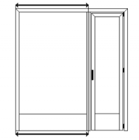
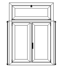
- Horizontal and Vertical dimensions: These refer to the width and height of a structure that is part of a composite typology.
Fichier:QuoteNodiLargCentroTraverso.PNG View of a horizontal dimension (width) measured from the frame edge to the center of the adjacent mullion. |
These dimension settings are supported by the following buttons:
 Starts dimensioning from the first structure on the right/top — useful for linear horizontal/vertical arrangements (e.g. ribbon windows).
 Starts from the first structure on the left/bottom — also for ribbon-type typologies.
- Fichier:Quotaverticale3.png Allows individual dimensioning of each structure.
- Fichier:Quotaverticale4.png Enables internal frame reference points for dimensions, as shown in the image below.
- Friction position: Defines the position of the friction mechanism (for pivot windows only).
- Hinge position: Position of the central hinge, applicable when more than two hinges are used.
 Hinge height is measured from the fixed frame, excluding the overlap flange.
 Measured from the moving frame, excluding the overlap flange.
 Centers the hinge height.
- Lower and Upper bolt dimensions: Height of the bolts (used for multi-sash structures). Reference is based on selected button settings:
 From fixed frame, excluding overlap flange.
 From moving frame, including overlap flange.
 From moving frame, excluding overlap flange.
 From moving frame to chamber.
- Mullion height: Height of the intermediate mullion.
 From fixed frame, excluding overlap flange.
 From moving frame, including overlap flange.
 Centers the mullion height.
Combined with the following buttons to define the reference point:
 From the frame (fixed or moving) to the start of the mullion.
 From the frame to the center of the mullion.
 From the frame to the end of the mullion.
Options
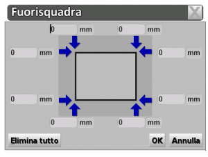
These buttons allow transformation of the typology into an arch, out-of-square shape, or porthole, and enable automatic equalization of glass or central mullion heights.
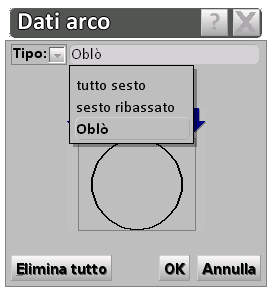
 : Transforms the typology into an arch or porthole. Opens the related configuration panel, explained below.
- Type: Select the type of arch or porthole to create:
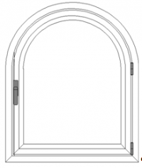
- Full semicircle: The arch radius is half the total width.
- Segmental arch: The radius is user-defined. The height of the radius must be entered.
- Porthole: Converts the typology into a circular shape. Only applicable to fixed, openable, or mullioned structures.
Fichier:Oblò.png Example of porthole |
- Fichier:TastovetriugualiV.png: Automatically equalizes glass sizes vertically (available from version 3.7).
The user must select the structures before clicking this button.
 : Automatically aligns central mullion heights across multiple structures. As with the glass option, structures must be selected first.
 : Allows correct placement of glazing bars (muntins) in multi-pane structures with varied glass dimensions.
| [[File:fogliodiprogett |
