How to make a compound profile
From Opera Wiki
Contents |
Avant-propos
The design of a curtain wall presupposes some actions in the profile archive and accessory archive that facilitate the construction of the structure in the Design Sheet.
It is important, for example, that compound profiles, which are widely used in this type, are loaded into the archive.
Un profilé composé est un profilé qui utilise des composants de différents matériaux et qui permet une gestion automatique des coupes, des couleurs et de l'usinage.
Before proceeding with the creation of a compound profile, the technical data of individual components should be checked. The main data to be checked or changed are as follows:
- Profile height
- Uses (fixed frame and mont./trav., in the case of a compound mullion or traverse profile)
- Glass system (must be curtain wall)
- Glass space (different for mullions and transoms);
- Chamber; Tooth; Thickness; Interc glass; Template.
- M/T type (in this box we can specify upright or traverse use)
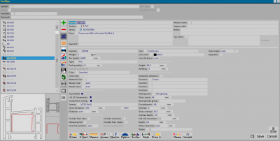
Whenever you need to create a compound profile, in the''profilearchive you need to check the Compound box, which will activate the Component Bill, Component Cut, Screws, and Screw Pitch boxes (these two fields should be filled in as needed) and the File:Componentkey.png button. Click on the File:Componentkey.png button to open the Profile Components panel.
Creating a spacer compound profile
One of the first steps in constructing a curtain wall archive is the inclusion of a compound profile that allows us to optimally manage the glass compartment. In fact, among the components of the compound profile mullion or transom (for the creation of which we refer to the next paragraph), we find an additional compound profile consisting of a series of spacers, the main feature of which is the variable Spv (measure of the glass-space of the profile in which the spacers are to be inserted). Let us see the procedure to be followed:
- Click the
 button to begin.
- Nome
 : type the Name of the profile or select it from the Profile Selection panel, which opens when the button matched to the field is pressed.
- Posizione
 : Choose the position of the compound profile (None or Internal).
- Tipo
 : choose the type (Spacer).
- Condizione: choose Interval as the condition type.
- Var./Da/a: choose the variable Spv and enter the measures for the range from a minimum to a maximum.
Repeat the procedure for each spacer whose use is possible in the compound mullion or transom profile.
The following table shows a range of possible spacers with corresponding measurements to be entered in the From/to boxes for the variable Spv.
In some cases the spacers to be used in the compound profile are paired and occupy the same glass space ('Spv). It is possible to enter these combinations as well, taking care to enter the spacer to be matched in the profile archive with the parent name (to make sure that the parent profile appears in the material list and cutting list).
In the name of the spacer we can enter the measure that indicates the positioning on the axis of the second spacer (see example figure: Name F50-DIST-12+8, where the first part of the name identifies the profile and +8, the measure of the spacer's axis positioning; Parent name F50-Dist-12, base profile).
In the spacer compound profile, we insert the paired spacer as in the figure opposite (F50-DIST-06 with Spv 28 to 30 and F50-DIST-12+8 with Spv 28 to 30):
Creating a compound mullion or transom profile
Let us see, now how to create a compound upright profile; the operations described below are also valid in the case of the compound transverse profile.
Suppose we want to create a compound profile for a curtain wall, the main component of which is a mullion:
- We press the
 button and enter the name of the upright we need.
- We define the position (Internal) and type (Main) and record.
We also do not need to enter any other data to avoid any conflicts with processing.
If the compound profile we are creating involves a transom it will be necessary to enter a value in the Fixed Difference field at both the presser and the cover, that is, a difference between the cut of the assembled profile and the component. This is because there must be nesessary clearance between the components to allow the water to pass through to be eliminated
We choose the other components below, following the same procedure: the cover, which by definition will have an external position and also an external type; the presser, for which it is not necessary to indicate a position but we can specify a type (in this case it will be Pressor); and, finally, the spacer (Position: None; Type: Spacer). We register and re-enter the Profile Archive.
After entering all the components and filling in the fields for the technical data of the profile, we press the File:Key-section.png button and open the Profile Sections panel, to view, and if necessary edit, the section of the composed profile.


