How to make a sliding typology
From Opera Wiki
Contents |
In the Archive Types framework click ![]() , then below select the File:Design.png button to open the Design Sheet framework. Click File:+inser.png to open the Type Selection framework, and following that click File:New.png, to enter the Structure Definition framework.
, then below select the File:Design.png button to open the Design Sheet framework. Click File:+inser.png to open the Type Selection framework, and following that click File:New.png, to enter the Structure Definition framework.
After setting the values for System and Series, select in the Structure field the type Sliding
Click the File:Mod.sides.png button, the program will wait for you to set a profile in the bottom side of the fixed frame;
Now click ![]() to put a frame profile in the bottom side. The adding profiles frame will be opened
to put a frame profile in the bottom side. The adding profiles frame will be opened
Where you will choose File:Telfisso.png.
This will open the Profile Selection panel where the frame profile can be selected.
After confirming with ![]() , we return to the Structure Definition Framework and select the
, we return to the Structure Definition Framework and select the ![]() button to have the program automatically put the same profile on the remaining 3 sides.
If it is a window with more than two sashes click on the File:Plus.png button to add space for another sash and on the File:Arrowdx.png button to switch to the left sash: the program will wait for you to set an outline in the lower side of the left sash.
button to have the program automatically put the same profile on the remaining 3 sides.
If it is a window with more than two sashes click on the File:Plus.png button to add space for another sash and on the File:Arrowdx.png button to switch to the left sash: the program will wait for you to set an outline in the lower side of the left sash.
Click on ![]() to put a sash profile in the bottom side, the add profile panel will be opened,
to put a sash profile in the bottom side, the add profile panel will be opened,
where you will select the File:Telmobile.png button. As we saw first, the frame selection panel of the movable frames belonging to the chosen system and series will be opened; look for the sash profile you prefer and confirm with ![]() , to return to the Frame Definition Panel.
, to return to the Frame Definition Panel.
Now click the ![]() button to have the program automatically put the same profile on the remaining 3 sides.
button to have the program automatically put the same profile on the remaining 3 sides.
Move to the right sash with File:Arrowdx.png and set a profile in the lower side of the right sash repeating the procedures described for the left sash.
Setting the brackets and gaskets on the perimeter of the fixed frame
Click on the File:Keyframe.png button, to assign the accessories related to the perimeter of the fixed frame, i.e., the brackets and gaskets (e.g., rebound balloon gasket and open joint center seal) the program will open the 'Fixed Frame Structure Accessories' panel; click on the ![]() button and the File:Code.png button: the Accessory Use panel will be opened;
button and the File:Code.png button: the Accessory Use panel will be opened;
Click on File:Square.png, the program will open the list of squares in the archive; search for the one you prefer and confirm, the program will return to the 'Fixed frame structure accessories' panel and click on File:Record.png
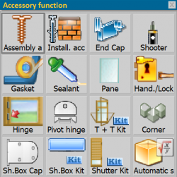
Click again on the ![]() button and the button located in the File:Code.png box: the accessory use pane will be opened, where you will select File:Gasket.png. The program will open the list of gaskets on file; search for the one you prefer and confirm, the program will return to the 'Fixed frame structure accessories' pane; click the File:Register.png button and the
button and the button located in the File:Code.png box: the accessory use pane will be opened, where you will select File:Gasket.png. The program will open the list of gaskets on file; search for the one you prefer and confirm, the program will return to the 'Fixed frame structure accessories' pane; click the File:Register.png button and the ![]() button to close the pane.
button to close the pane.
To set the brackets and gaskets on the perimeter of the movable frame, we select File:Keymobile.png and repeat the steps described above for the fixed.
Assignment of water drain plugs on the fixed frame and handle in the sash
- Click the File:Arrowdx.png button until you are sure you are positioned in the fixed frame and select the accessories button .
- Click on the
 button and the File:Code.png button.
- In the accessory use frame choose File:Cap.png, the program will open the list of accessories stored as caps; search for the one you prefer and confirm; select the File:Record.png button and
 to close the frame.
In the same way you proceed to put, for example, mounting accessories, tray handles, etc...., keeping in mind that you must always move with the File:Arrowdx.png button to switch from fixed to movable, and vice versa, and place the accessories in the part you are interested in. Now the window should be drawn in the Design Sheet: the structure becomes a type.
After you have finished defining the structure, click on the File:Record.png button you will find in the upper right-hand corner, which will allow you to confirm the structure you have created and draw it in the Design Sheet; the mouse pointer has changed appearance: now point to the upper left, click then release; drag the mouse crosswise to the right, from top to bottom, until the type is sized, as in the figure:
Now click the File:X.png button to return to the general data for the type; in the 'Name' box, type a name for the type (e.g., FIN2A); in the 'Pers' (Customization) box, type a customization of the code, if you wish (e.g., FIN2A); in the 'System' and 'Series' boxes, type a system and series, respectively, under which you want to register the type (these boxes should already be filled in by the program.: Z-frame - Open joint); in the 'System' and 'Series' boxes, respectively, assign the system and series under which you want to record the type (these boxes should already have been filled in by the program); in the 'Desc' box, type a description for the type (e.g.: 2-pane window); in the 'Labor minutes' and 'Laying minutes' boxes, respectively, type the minutes it takes to perform the installation then the minutes it takes to lay the typology; now click the File:Record.png button to record the typology in the archive.


